Local Storage seems to be disabled in your browser.
For the best experience on our site, be sure to turn on Local Storage in your browser.
G-NiceRF| SK108U|1W PC remote control & serial control switch RF module
SK108U includes SK108U-Tx and SK108U-Rx. SK108U-Tx is an industrial serial control transmitter, it works with SK108U-Rx to build wireless switch control system. SK108U-TX is a serial interface which can connect with PC and other serial devices. One SK108U-Rx has 4 channels relay output. One SK108U-Tx can control multiple SK108U-Rx. The frequency of the SK108U-Tx and SK108U-Rx can be set to avoid frequency interference. In hardware, SK108U-Tx is the same as our SV series module, which has different output power and different interface for option. SK108U-Rx is same as SK108 in hardware but different firmware

Features and application:
Features:
-
Up to 3Km line-of-sight in open area
-
Frequency Band : 433 ,470,868,915MHz(Optional)
-
16 predefined channels
-
Parameters configurable by PC software/ Remote controller/ UART Command
-
Real-time/Timing working mode for optional
-
GFSK modulation
-
Bi-directional wireless switch control
-
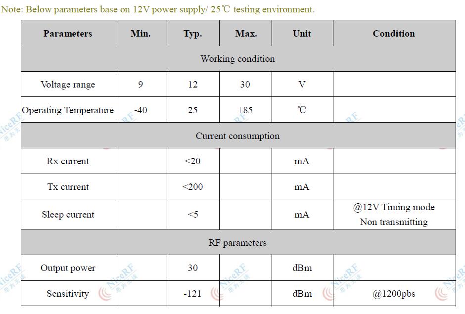
Sensitivity up to 121 dBm
-
Maximum output power: 1 W
-
Indicate and alarm when battery low
-
Working voltage 9 ~ 30 V
-
Working temperature range: - 40 ~ + 85 ° C
-
Weight: 143g
Applications:
-
Remote control switch control
-
Security system
-
Home automation remote sensing
-
Wireless remote telemetry
-
Building automation and security
-
Access control system
Specification:
Electrical characteristics:
Functional description:
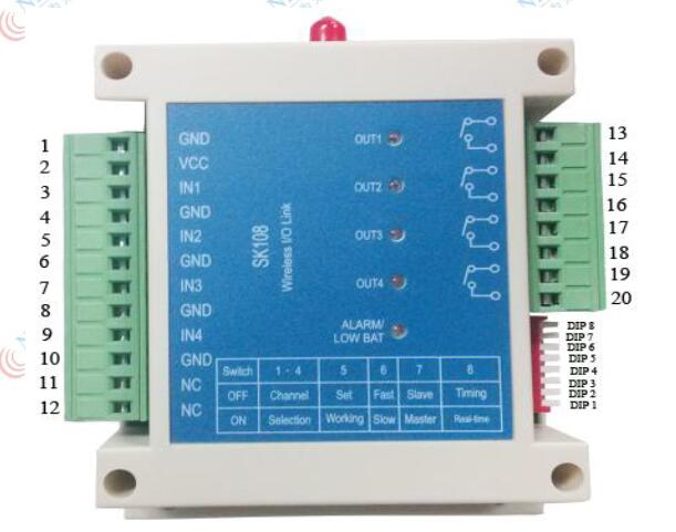
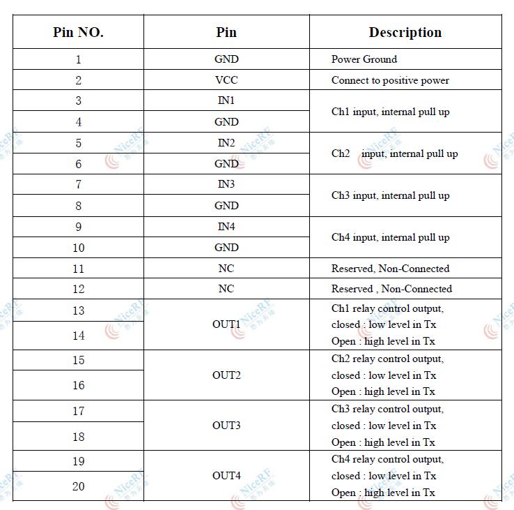
The description of interfaces as below:
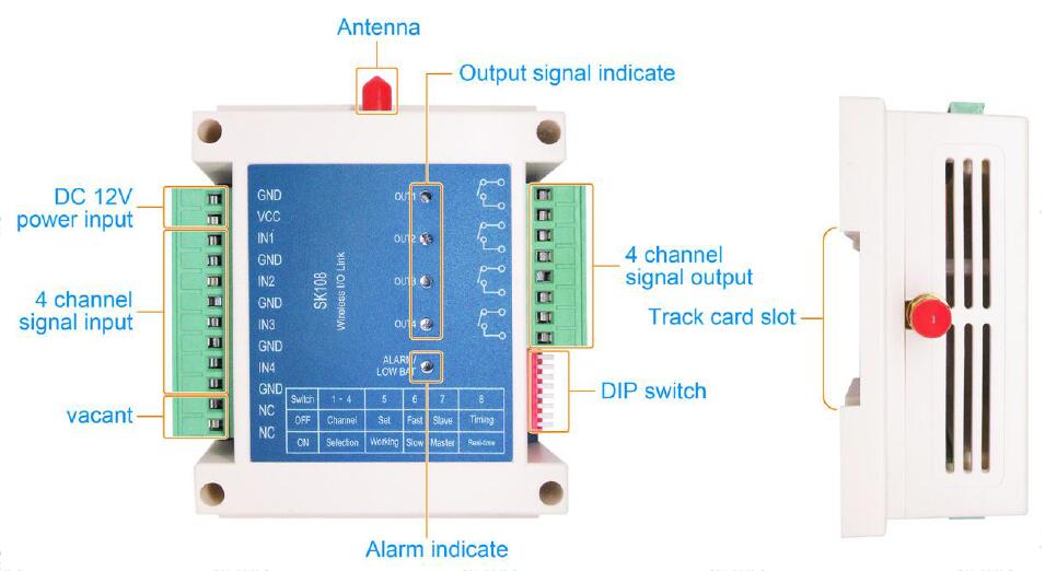
Application Connection:
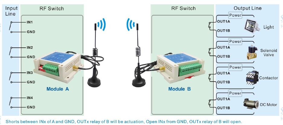
The input port is pulled up internally, leave open or connect with 3.3V will result in a high level, it is low level when connecting to GND.
A high level will make the output of the other side short out. And low level will make the output of the other side open. Below is a regular connection:
Dip switch Settings (valid when power on again )
DIP8 - Normal working mode selection
ON - Real-time mode ( In this mode, when state changes in input port, it transmit signal immediately)
OFF - Timing mode (Signal transmitted at the predefined time interval according to the setting of DIP6)
DIP7 - master/slave selection
ON - the master
OFF - the slave
DIP6 - Time interval selection of timing mode
ON - Slow time (configurable, default 30S)
OFF - Fast time (configurable, default 2S)
DIP5 - Mode selection
ON - Normal working mode
OFF- Setting mode (Wireless setting on PC via configuration module K108-S)
DIP4~1 - Working frequency channel selection, total 16 channels(default channel interval: 0.5M), frequency is configurable through PC software / UART Command/ Remote controller SK108.
Real-time Mode
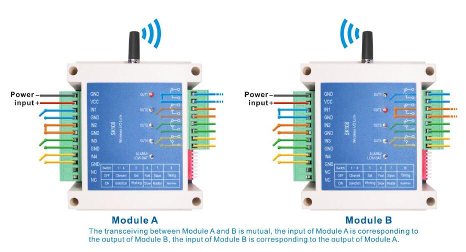
In real-time mode, it is bi-directional communication. The change of input will be synchronized to the output of the module in another side.
Each module has four independent input and four independent output. In real-time mode, the change of an input of the four channels will trigger the transmission, in another side, the corresponding relay of the module will be synchronized after getting the signal, then it returns an acknowledged signal. If not acknowledged signal comes to the triggered modules, the alarm LED will light on. All the output relays will be resumed open if no acknowledge signal received for continuous 3 times inquiry.
For example, communication between modules A and B,
the 4 output of module A is corresponding to the 4 input of module B,
the 4 output of module B is corresponding to the 4 input of module A, shown as below:
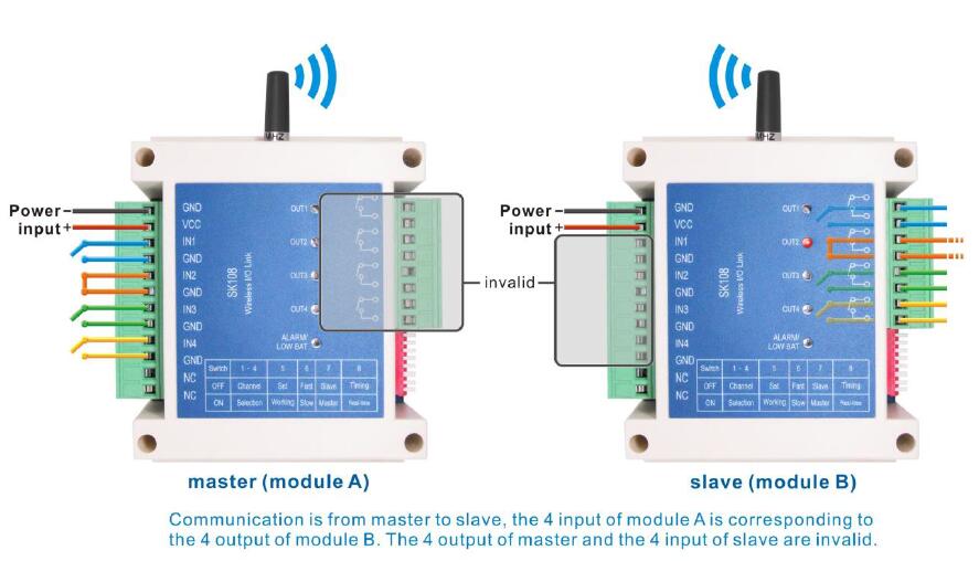
In real time mode, the modules worked in master mode, and the other side worked in slave mode. The slave module will send an inquiry signal at a fixed time interval, the master will send the synchronized message accordingly. The alarm LED will light on and all the four output relay will resume to 0(all relays are in open state)if no synchronized message received for continuous 3 times. The LED will indicate low battery and all the four output relay will resume to 0(all relays are in open state)if get low battery signal from the other side;
Note: Under this working mode, please don’t power on the master and slave at the same time.
Timing Mode
In timing mode, the module works in master mode or slave mode. The communication is one way. Communication is from master to slave. The master transmits the wireless signal to the slave regularly, the corresponding relay of the slave will be synchronized after got the signal.
The module can be worked in fast mode or slow mode by changing the dip switch. The time interval of the fast or slow mode can be configured by PC software (default is 2s in fast mode, the 30s in slow mode). The alarm LED will light on and all the four output relay will resume to 0(all relays are in open state)if no synchronized message received for continuous 5 times interval. The LED will indicate low battery and all the four output relay will resume to 0(all relays are in open state)if get low battery signal from the other side;
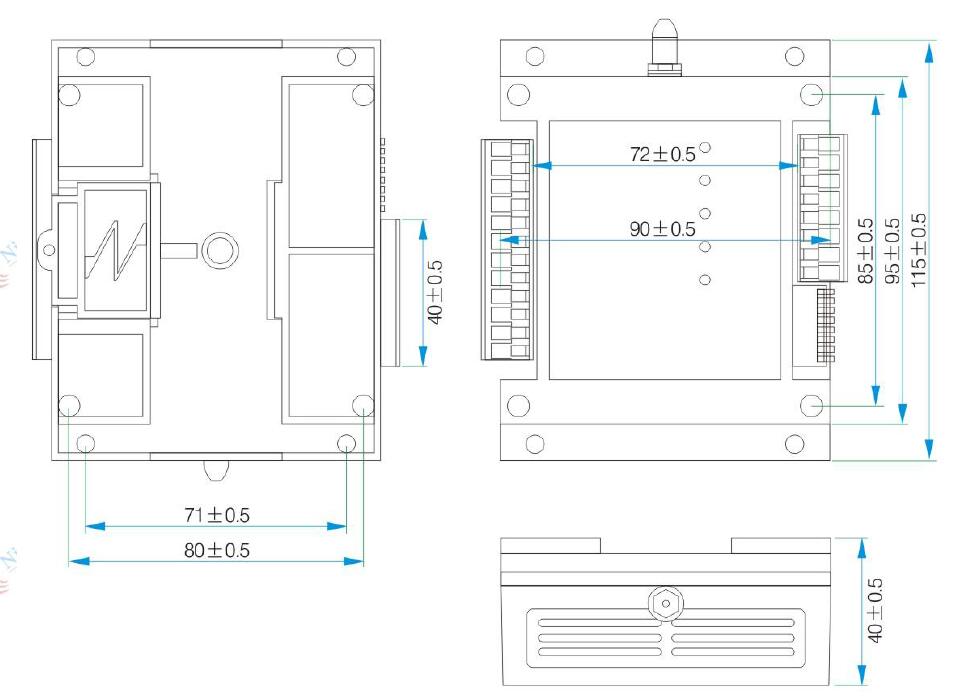
Pin and dimension:
Pin definition:
Mechanical dimension:
| Subtitle | N/A |
|---|---|
| UPC/EAN | 4604046161419 |
| Count | N/A |
| M.R.P | ₹7,000.00 |
| Brand Name | G-NiceRF |
| Model | N/A |
| Whoesale | Available |
| Dimension | 18X9X11 cm |
| Working voltage range | 9~30 V |
| Supply Voltage | N/A |
| Receiving current | <20 mA |
| Receiving sensitivity | -121 dBm |
| Operating Temperature Range | N/A |
| Operating Temperature | N/A |
| Maximum output power | 1 W |
| Standby current | <5 mA |
| Distance (Range) in KM | 3Km in open area |
| Data Rate | N/A |


